Gallery of Mercedes Engine images

"For the first time in nearly 100 years a brand new Mercedes 180 HP engine has been built from newly manufactured parts by The Vintage Aviator Ltd."
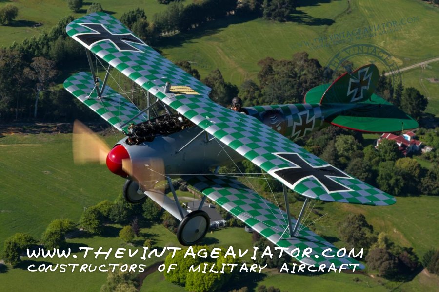
The D.III is an inline 6 cylinder of 15000cc, has a 140mm bore and a 160mm stroke. It produces 180HP @ 1400RPM and it was a favourite of many of the aircraft designers in Germany during the First World War. These engines were favoured because they are very reliable in operation and powerful, the exhaust note tells you it means business! The Vintage Aviator is dedicated to building exact reproductions of First War World aircraft, using either original plans or reverse engineering surviving musuem examples. Installing the original powerplants is a vital part of these projects – but sourcing the engines is often much more difficult than the airframe construction plans. Over the last few years, we have undertook the building of exact reproduction engines. This allows us to build aircraft that would otherwise be impossible to put back into the air under their own, historically correct, power. Our BE.2’s, RE.8’s, Fokker D.VIII’s and Sopwith Snipes have all been powered by TVAL new built engines. The existence of those engines also opens the door to the possibility of building other aircraft types using the same powerplants. With so many German aircraft using the Mercedes, exciting potential projects based on those aircraft have been put on the back burner while engines were sought. Over the years, we have managed to obtain only 2 original 180hp Mercedes engines. Many exist in museums, and a few are rightly prized by private collectors. There are just not enough “in circulation” to allow us to realisically pursue many of the German aircraft projects we’d love to tackle. Several years ago, encouraged by the success we had building relatively “simple” engines such as the RAF 1A or Oberusal, we decided to commence what became a very long project to reproduce the 180HP Mercedes. From the onset it was obvious that creating a new build Mercedes 180HP engine was not going to be an easy task. Only a handful of these engines have survived despite thousands being produced and no complete set of factory drawings seem to exist.
 Without the original drawings any manufacturing job becomes increasingly difficult. The sheer size of this engine and the fact that there are many unique sub assemblies and accessories that need to be made if you intend to actually run the engine, confirm this job would take years to complete. The difficulty is compounded because these engines are by no means primitive and include a number of complex components; the oil pump assembly alone for example makes up 30 of the 600+ drawings the team at TVAL had to create. The original designers certainly understood what they were trying to achieve with these engines. They incorporated things like the overhead cam and roller rockers – innovations that are still employed on modern engines almost 100 years later. As weapons of war, these engines employed some of the latest technology and were designed by some of the top engineers of the time, manufacturing techniques were state of the art and the materials used were often the best available. Even by today’s standards this engine build would be very challenging for a well equipped shop. TVAL’s experience with Mercedes engines started with the overhaul of a number of originals, for ourselves and other collectors. All required significant work and numerous missing, damaged or worn out parts needed to be manufactured. In addition to the “new” parts, a number of “consumable” parts needed to be made to facilitate the overhaul process and provide ongoing support for these engines. The consumable parts include; piston rings, gaskets, gudgeon pins, pistons, valves, valve springs, spark plugs, various gears and even cylinders. As this list of parts grew, so did our determination to recreate the entire engine. The first step would be to create 3D CAD models of the Mercedes 656 unique parts, and then draft a full set of manufacturing drawings. The digital models allowed many potential assembly problems to be resolved before manufacture started and did away with the need to build an expensive prototype. The best way for TVAL to collect this data was to disassemble one of our original engines and digitize every single component. This process alone took nearly two years. Armed with a complete set of drawings and digital models of nearly every part, we then needed to develop the manufacturing processes and also determine exactly what materials were to be used. This would account for another few months of research -samples of various parts were sent to labs around New Zealand to determine the exact material composition and to allow for modern substitutions if the original material was no longer available. One of the most interesting aspects of this project was the unique mix of aerospace engineering’s oldest and newest technologies.
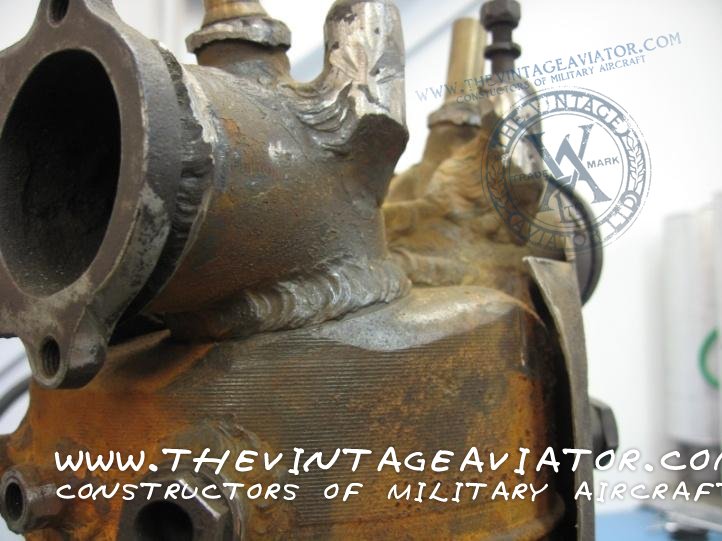
Traditional methods such as fitting and turning, sand casting, welding and sheet metal work were combined with modern rapid prototyping techniques, Xray technology, CAD modelling, CNC machining and non-destructive testing to produce all of the parts required. Manufacturing methods from 1916 would require some detective work. For instance; brazing aluminium to steel and welding pistons together from steel and cast iron required techinques previously unknown to us. After resolving most of these unknowns, the decision to proceed was made and work commenced to build new Mercedes parts and complete engines. These engines can easily be considered “works of art” today. They were never designed to be built by modern machinery, and even though there are a large number of machined parts in these engines that can easily take advantage of modern CNC machines, a substantial amount of time has to be spent hand-forming various items. Parts such as the cylinders are made up of a welded cylinder head combustion chamber assembly that is then screwed onto a machined cylinder barrel and welded in place. This assembly is then surrounded with a hand-formed sheet metal water jacket, made up of three separate parts, welded in place around the barrel. The intake manifolds, like the water jackets, were hand-formed from sheet metal and incorporate a second layer to create a water jacket for the manifold heating. The team at TVAL manufactured a number of jigs and press tools in order to construct these items and had to come up with some innovative ways to achieve some of the more difficult and challenging shapes required. Many tests were carried out before suitable production parts could be manufactured, each unsuccessful test required the press tools or jigs to be modified or redesigned completely.
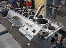
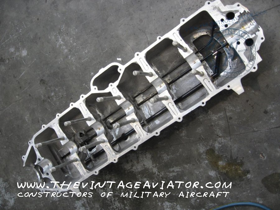
TVAL always makes every effort to reproduce aircraft and engines just as they were made nearly 100 years ago, using the same materials and using the same design. This means the TVAL built Mercedes engine parts are interchangeable with the original parts – hopefully allowing some of the incomplete original engines around the world to be successfully restored to working order. We did however, make the decision to manufacture three main components differently to the original part. The cylinder heads, cam housing and water pump impeller have all been manufactured in ways that allowed us to save time by utilizing manufacturing techniques we have at hand in our workshop. The individual cylinders of this engine are very time consuming to manufacture and require a number of special jigs to make sure they will fit, we chose to eliminate some of the manual assembly by casting the entire cylinder head in one piece rather than building it up from many smaller parts and having to weld them all together. This also allowed us to carry out much of the machining of the cylinder head using a CNC 5 axis machining center. The overhead cam housing and the water pump impeller were both parts that were originally cast but we decided to fully machine these instead. Once the part is digitized we have the ability to go directly to manufacture with one of our CNC machines. The water pump impeller is intricate and requires two “set ups” to completely machine it from a chunk of raw material. The cam housing had to be modelled for CNC machining anyway, so we decided to fully machine it from a long piece of steel bar rather than having to use a foundry and having to make a casting pattern which would need to machine after casting anyway. At the start individual parts are made they then need to be built up into larger assemblies: The two crankcase halves were without a doubt the most problematic parts to recreate. In fact, their complexity was the reason we almost didn’t go ahead with this project. It was difficult to even accurately measure such a large aluminium casting, let alone digitize it with the equipment we have. Our solution was to scan the halves with a coordinate measuring machine which allowed precise measurements to be taken at various points and then complete the digital model in the computer using CAD software. The crankcase is cast in two halves split along the crankshaft centre line. Each half has a number of under cuts and hollowed areas; a real testament to the casting abilities of the engineers of old, and needless to say a real challenge for the engineers of today. The lower crankcase half incorporates a large plenum area that forms part of the air intake; this is to warm the intake air to help combat icing – one of the common problems with aircraft engines. The oil sump forms a portion of the lower crankcase and has a number of steel oil lines that must be assembled in place within the casting, these lines carry oil from the oil pump mounted in the sump to various parts of the engine including each main bearing.
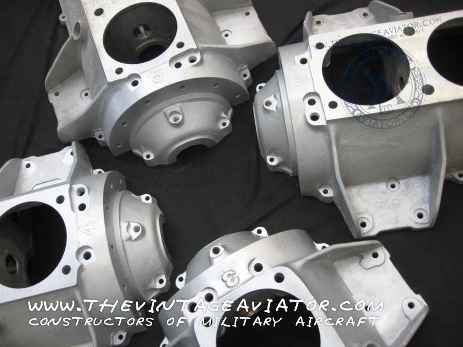
 The sheer size of this engine would create problems in manufacture as well as measurement; this casting was large, intricate and required a large volume of molten material to fill the pattern and flow to numerous small cavities during the casting process. This was no job for an inexperienced foundry, we needed advice on all aspects of casting in order to obtain the best results and not waste time or money. We learned about “chills”, “risers”, “gates”, “pop-ups”, “sprues” and “dross” every aspect of the casting process and gained an all new respect for the craftsman that poured what must have been a huge crucible full of molten aluminium at roughly fourteen hundred degrees Fahrenheit! After casting the crankcase still presented problems in machining because of its 1.3 metre length. An extra-long line-boring bar was manufactured to accurately machine the white metal main bearings. The crankshaft measuring 1.5m long was machined from a billet weighing over 500kg, but once machined the finished crankshaft weighs a little over 34kg. There aren’t many engine rebuilders used to handling a crankshaft of this length or mass, so TVAL ended up purchasing an old crankshaft lathe and modifying it to suit the task at hand – this kind of lateral approach tends to be a Kiwi tradition. The requirement to remove so much material, and the size and length of the crankshaft made its manufacture a long and difficult task. Another problem the extreme length created was that it made the crankshaft relatively flexible and therefore time consuming to machine. When considering the advances in machinery and the difficulties we faced with making this part, we gained yet more respect for the engineers of the day. The cylinder assemblies each have just two valves that run in phosphor bronze guides. The valves themselves are huge and odd in the sense that the stem is threaded to allow for adjustment. The helical valve springs are tapered and the spring retainer is held in place by a split collet that screws onto the threaded valve stem. The cylinders are all individual steel units interconnected by small rubber seals that allow the coolant to flow from cylinder to cylinder, this means that even the hand welded fittings and water jacket must be constructed with the cylinder in a fixture that maintains this important alignment.
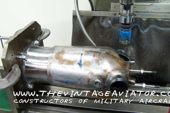
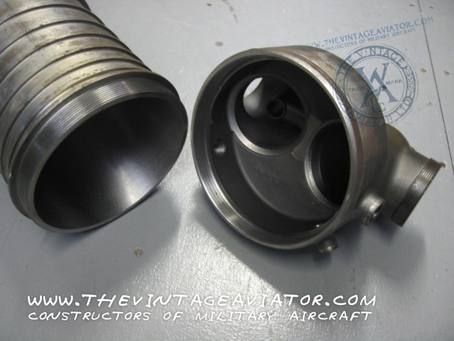
Each cylinder has two spark plugs and a priming cock. Each piston is made up of two parts; the crown is made from steel and the skirt is made from cast iron - these are screwed together and then welded. Each massive piston weighs in at approximately 2.7kgs. The “I” beam style connecting rods use white metal bearings at the big end which are pressure fed via the crankshaft. In order to get the oil from the big end to the pin end, an oil pipe is fitted on one side that supplies oil to unusual steel fully floating gudgeon bushes. To create the white metal big end bearings, molten metal is poured onto a bare bronze bearing shell and later machined to size. The camshaft is a hollow section and runs in four pairs of brass bushes which are bolted around the camshaft journals. This assembly is then inserted into the main cam tube which also forms the housing for the valve rockers, this whole assembly is bolted to the top of the cylinders. The camshaft is driven via a tower shaft running up the rear of the engine, the engineers cleverly made this tower shaft adjustable enabling perfect meshing of the gears. The valve rockers use a roller to follow the camshaft lobes and the exhaust lobes incorporate an added feature to aid in starting. Each exhaust lobe has the addition of a decompression lobe. This lobe is brought into use via a lever that when pulled, draws the camshaft toward the rear of the engine and lines this lobe up with the exhaust rocker which in turn opens the valve slightly to give half compression. This “decompressed” position allows for much easier starting by the grateful ground crew, who would otherwise certainly sweat trying to swing the nearly nine foot diameter propeller. The main cam housing was a tricky part to manufacture because of its length, it required special tools and a fresh approach to machining. Originally a casting, we decided to machine this part from solid and do away with the need for another set of casting patterns and the related cost. At the front of the engine connected to the cam housing is the air pump, used to pressurize the fuel tank - this assembly alone is a masterpiece of engineering. The air pump is essentially a small one or two cylinder piston pump. At the opposite end of the camshaft is the decompression lever, and combination tachometer drive and interrupter gear for the machine guns. No seals of any sort are employed around the valve rockers, just a precision fit in the cam housing. As a result, a certain amount of oil leaks out and is usually blown back into the pilots face due to the overhead mounting of the camshaft. The essential accessories for each engine are nearly as complicated as the engine itself, and each of these components also needed to be reproduced because spares simply don’t exist. These include the centrifugal type water pump, unique oil pump, piston type air pump, altitude compensating carburettor and a number of bevel gears to drive many of these accessories. The oil pump incorporates a large number of parts and was quite a task in itself to manufacture.
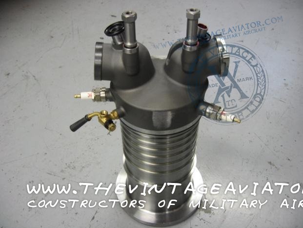
 The pump body is cast bronze and has a number brass tubes that connect oil passages linked to the four plungers that perform the required tasks. These plungers are connected to a bronze crankshaft driven from the rear of the engine by a worm gear. The pump has a number of circuits - the first acquires oil from the sump at the rear, and supplies oil to the main and big end bearings, as well as the camshaft bearings. The second circuit scavenges oil from the front sump and returns it to the rear. The third maintains the level in the main sump and returns the excess to the oil tank, while the fourth draws fresh oil from the oil tank which is added to the main supply to the bearings. The oil system also employs a pulsation damper which cushions out the pulsations caused by the oil pump plungers. The carburettor is a twin throat altitude compensating carburettor which is water heated. This double barrel rotary slide valve carburettor is divided so that each barrel supplies the air/fuel mixture to 3 cylinders. The carburettor float bowls are equipped with filters and independent float chambers. TVAL cast and machined these units to exactly reflect the original items, and in operation they perform very well. The brass rotary valves proved difficult to manufacture as they are very close in tolerance and extremely thin section. This carburettor is very well designed, and while it does not employ an accelerator pump it has a unique auxiliary air regulator. This air regulator allows automatic mixture control during rapid acceleration by way of a sliding ring that exposes a set of auxiliary air inlets, all very reliable and very clever. One of the first steps in manufacturing is understanding the individual parts and also the processes necessary to create them. Once the parts are made, the final step is assembling the entirety of parts into a working product, in this case an engine as robust and powerful as the original. TVAL’s low volume of production allows us to inspect every single item with the appropriate non-destructive testing (NDT) method. Once a part passes this rigorous quality assurance program and we are certain it conforms to our drawing only then it can be fitted to an engine. This testing and our dedication to faithfully reproducing the original components is our own form of insurance. A build record and paperwork package is started at the very beginning of manufacture, this will accompany the engine throughout the build process and during test running. Once all of the parts have been made and inspected they are ready for assembly.
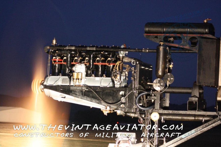
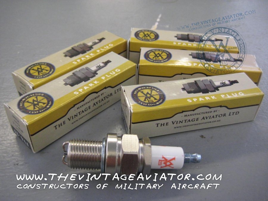
 This always starts with cleaning; ultrasonic cleaning as well as solvent based, and a pressurized hot tank with a gentle detergent to finish things off. After cleaning, parts are measured again and sometimes sized or balanced. The main bearings are white metalled and then machined to size with a special line boring machine. Each part is checked for proper clearance and fit, over and over again. Detailed measurements are taken with calibrated tools and recorded in the build record which becomes a sort of pedigree for the individual engine. Bolts and nuts are tightened to specified torques and usually locked by some mechanical means. Starting with the upper crankcase mounted to a custom stand that allows the engine to be turned upside down, the new engine takes shape. Rotating the engine upside down makes it easier to install the crankshaft, conrods, pistons, water pump and oil pump. Positioned upright to complete the assembly, the cylinders are next to be bolted on. Once all of the cylinders are in place the cam tube assembly can be installed on top of the six cylinders. With the engine taking shape, the magnetos are then installed, the ignition wires and our own TVAL manufacture spark plugs can be fitted. The carburettor spark advance linkage and plumbing is attached and checked for proper operation before the intake manifolds are built in place. The intake manifold is usually custom built in order to make sure it is an exact fit. Once assembled the newly manufactured engine must undergo a rigorous test program specifically designed to turn up any material or manufacturing problems. For the “First of Type” TVAL runs the engine for at least 25 hours on our purpose built engine test truck then completely strips and measures nearly every component and checks for wear, cracks, interference and overall performance. During each test run monitoring devices provide the critical data necessary to assess the engines performance; such as cylinder head temperature, oil temperature and pressure, exhaust gas temperature, coolant temperature, fuel flow, RPM and torque.
 The ambient conditions are recorded along with each test run and a log is kept in order to document our results. Our first reproduction Mercedes engine passed all of our tests and exceeded our expectations for performance. The parts were all checked and the engine re assembled once again for a final production test run of two hours and then installation in our latest Alabatros DVa. A number of new build engines are planned and already underway, allowing TVAL to bring to life a number of extinct great war fighters. As I said at the beginning of this report, attempting to build a new reproduction Mercedes engine was never going to be easy, and it certainly wasn’t! I would hate to think how many hours went into researching, drawing, assembling and testing this engine, but the rewards are certainly sweet when you stand back and listen to the deep rumble of an engine recreated almost 100 years after the first units came of the production line. It is a real pleasure to be working with such a great group of highly skilled and experienced people, everything they do is quality. Each one is built with pride and passion. For all it’s complexity, the engine is really only a means to an end. Each of the Mercedes D.III reproduction engines manufactured by TVAL will be installed in an exact copy of a Great War German aircraft over the coming years. Many of them will be examples of aircraft unseen in the skies for nearly a century, and that’s what we look forward to – seeing our engines bring history back to life.
