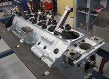
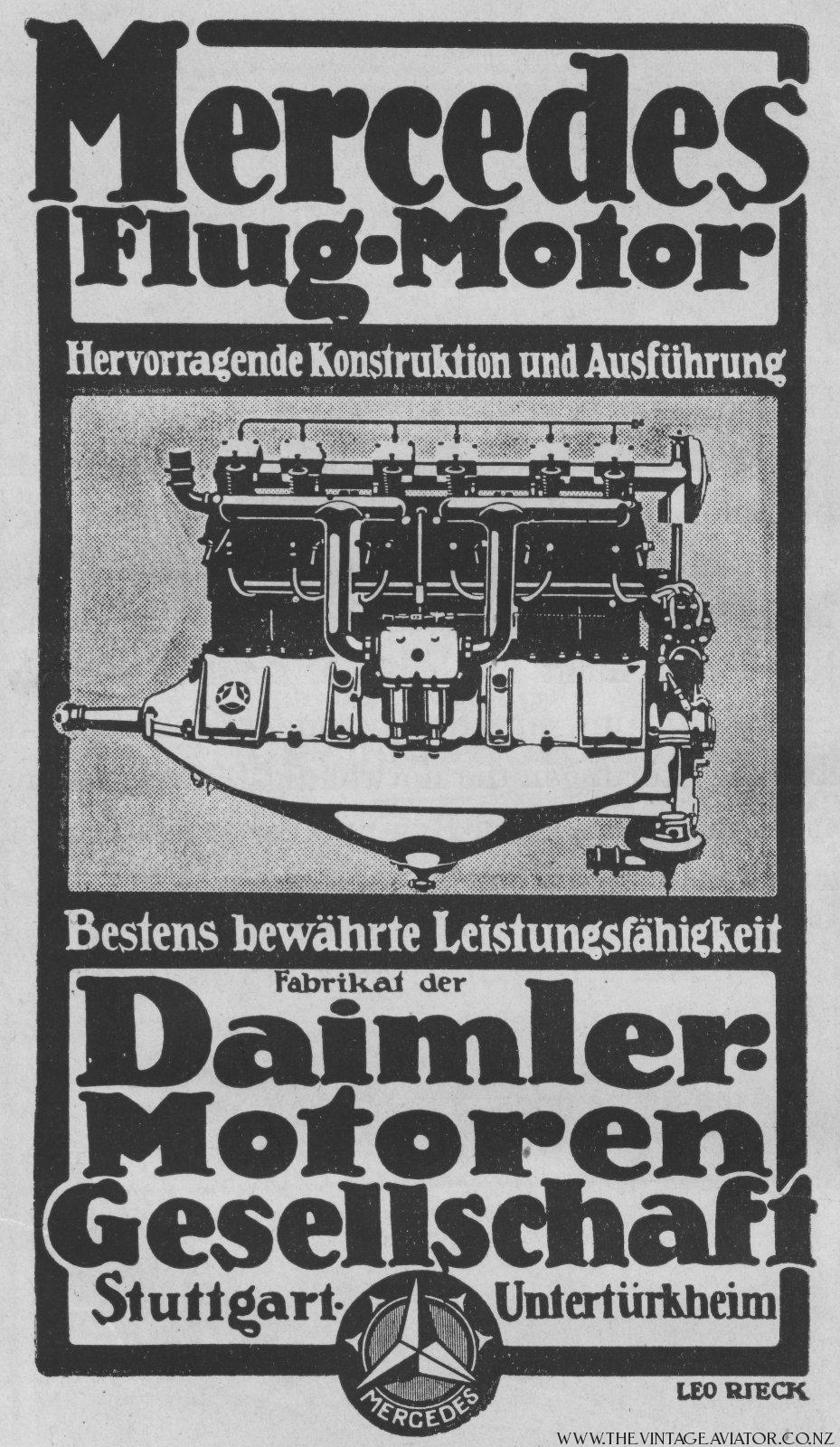
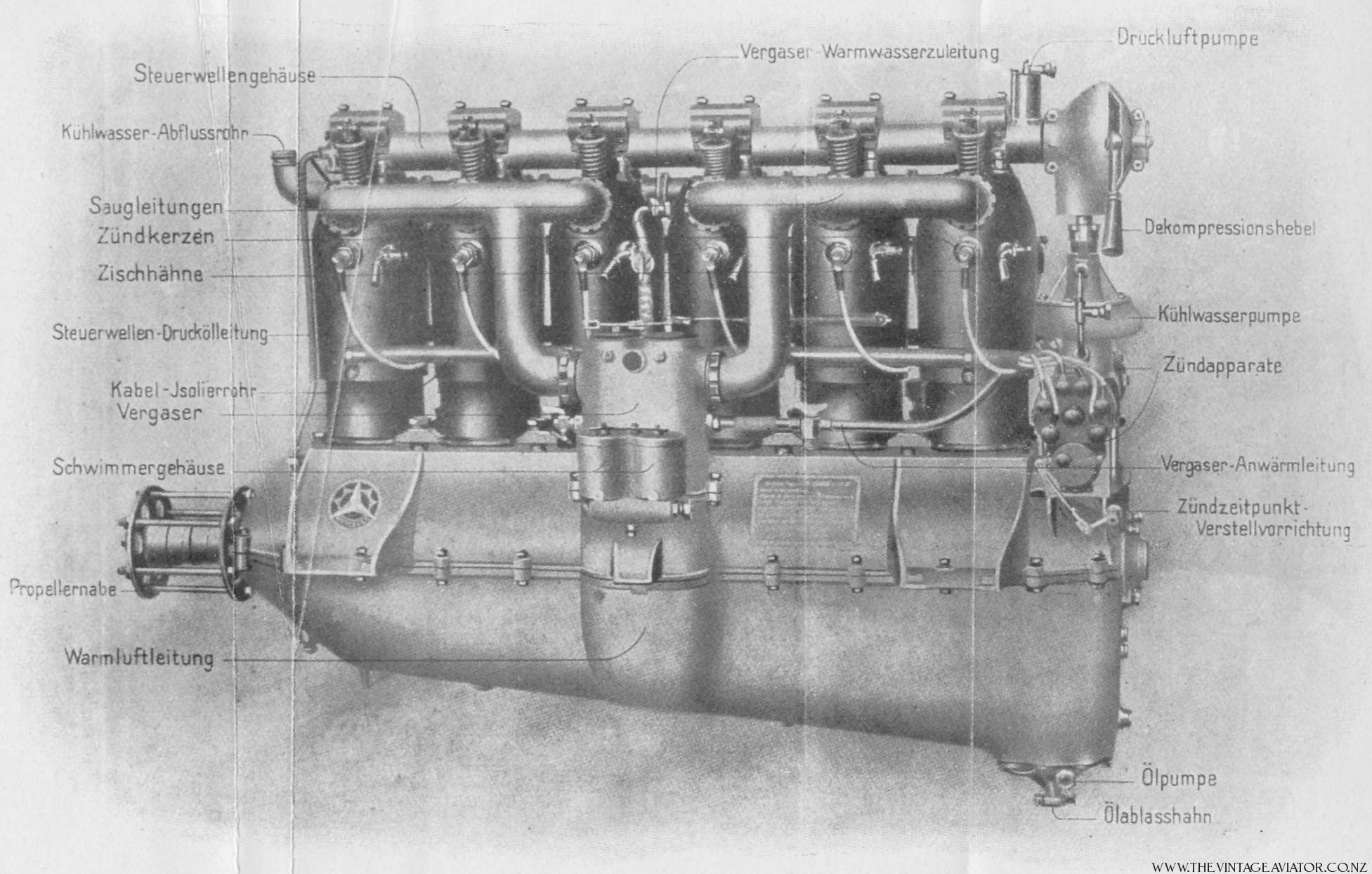
Gallery of Mercedes Engine images

‘‘In 1914 Daimler provided the Imperial Air Service with what was to be their most prolific and successful engine, the Mercedes D.III.’’
When introduced this engine was too powerful for most aircraft and was not put into service until 1916 with the Albatros series of single seat aircraft. Originally rated at 150 hp, by the war’s end this unit produced 217hp @ 1,750 rpm. Following the design philosophy first introduced by Daimler with the D.1 of 100hp, the Mercedes provided a robust, light and powerful design. The ‘D’ series engines are water cooled, in-line six cylinder, upright engines. Early engines had three sets of paired cylinders. With the introduction of the D.III, the design changed to individual cylinders allowing for more economic repair. Cylinders are machined steel with two piece fabricated steel water jackets. Each cylinder is bolted to the upper crankcase with four studs that engage flanges on each cylinder base.
The crankcase is cast in two halves split along the crankshaft centreline. The upper half is quite complex providing the top half of the main bearing journals, mounts for the twin magnetos, plenum for the carburettors and mounts for the vertical jackshaft that drives the camshaft and ancillaries. In addition, each of the six engine mounts are cast into the upper case. Some late model engines also had a mount for a generator cast onto the port side, at the rear. The bottom half is the primary reservoir for the wet sump lubrication system. With the D.III series the sump sloped to the rear where the oil pump is situated unlike the D.I and D.II that had a centralized sump cavity and pump. There is an external oil tank that allows for a replenishment of the oil.
1.Overhead camshaft with rocker fingers operating directly onto the single inlet and exhaust valves. The camshaft was driven by the crankshaft using a series of bevel gears and a vertical jackshaft at the rear of the engine. Ancillary equipment, while changing position over the variants, were all driven from the jackshaft. These ancillaries included: oil pump; water pump; magnetos; compression release.
2. Individual steel cylinders bolted to the upper crankcase. In an era of cast iron or iron lined aluminium cylinders, the use of steel created a much lighter cylinder. Each cylinder had a sheet steel water jacket that enclosed it. Water jackets were interconnected with flexible lines to provide a continuous water flow system.
3. Dual ignition and dual sparkplugs driven by 2 Bosch magnetos. One magneto was used for the port side plugs and the other for the starboard side. Most D.III engines used ZH6 model magnetos.
4. Cast iron pistons with drop forged steel domes that were threaded and then welded into place. Since the bore did not change over the D.III range, this allowed for a straight forward approach to an increase in compression by only having to manufacture a new dome. Rings were accommodated in the cast iron piston skirt.
5. Self starting utilising the Bosch hand starting magneto situated within the cockpit.
6. Average weight of 660 lbs.
7. Long stroke engines with a bore of 140mm and stroke of 160mm.
8. One dual Mercedes twin jet carburettor. The carburettor is mounted on the port side of the engine. Later models of carburettor were larger in depth. On the Fokker D VII this necessitated a modification to the port upper engine bearer strut requiring relocation outboard of the primary welded cluster. This is one of the identifiers to the age of a specific D VII airframe.
9. Carburettor mixture pre-heating was designed into the intake system. While warm mixtures will reduce the power output this was not as critical as the prevention of icing at the altitudes where these engines thrived. The lower crankcase design allowed for the passage of air through the openings in the case into the intake. Like many good engineering practices this single solution had two benefits: it warmed the intake charge to prevent icing and cooled the oil in the wet sump. To further assure an even mixture, the carburettor body is water jacketed.
10. De-compression setting. On the rear top of camshaft is fitted a de-compression lever. This was provided to ease the starting of what was considered a high compression engine. When rotated, the lever slightly rotated the camshaft allowing for a slight opening of the valves which would reduce the compression. This was a manual lever not accessible from the cockpit.
Early engines like the Daimler are fascinating. Internal Combustion engines were quite new as was aviation. Many aspects of what we consider to be current engine technology were unheard of then. Even so, it is interesting to see how little some concepts have changed. For example, the overhead camshaft was not common. Most engines used pushrods to actuate valves. If you inspect the exposed valve train of a WWI Daimler and then look at a current straight six BMW engine you will see the same type of rocker valve actuation. Rocker arms running directly off the cam lobe and on to the valve stem. Following is a table showing the genesis of the D series engines from Daimler.
Note: When researching historical power output levels, there are discrepancies based upon the information source and how they evaluated the engine. Imperial Air Service ratings for in-line engines were all calculated at 1,400 rpm and do not necessarily indicate maximum output. These are the values shown below.
Introduced in 1913
100 hp
paired cylinders
central oil pickup and sump
water pump at bottom of rear accessory stack
Introduced in 1914
120 hp
paired cylinders
central oil pickup and sump
water pump at bottom of rear accessory stack
Introduced late 1914
160hp
separate cylinders
rear oil pickup and sump
water pump mid height on rear accessory stack
compression: 4.5:1
Introduced 1917
180hp
separate cylinders
rear oil pickup and sump
water pump at bottom of rear accessory stack
compression: 4.64:1
Introduced 1918
200hp high altitude version
separate cylinders
rear oil pickup and sump
water pump at bottom of rear accessory stack
new carburation
new fuel blend
compression: 5.73:1
The Daimler engines were considered to be reliable and robust engines. Easy to run and light on maintenance compared to the rotary engines of the day. These strong in-line engines allowed pilots to focus more on flying and combat and less on engine handling. While rotary engines were strong, light and powerful in the early years, the more powerful they became, the more torque they generated and the more skilled a pilot needed to be in order to control his aircraft.
The linear thrust of the Daimler engines and the relatively low torque impact on the handling characteristics allowed a greater number of pilots to become effective combatants. In general terms aircraft are designed around the powerplant. Arguably the most effective single-seat aircraft to come out of the first war was the Fokker designed D VII. The D VII was powered by all variants of the Daimler D.III engine and was always a force to be reckoned with.
John Weatherseed, 2008
