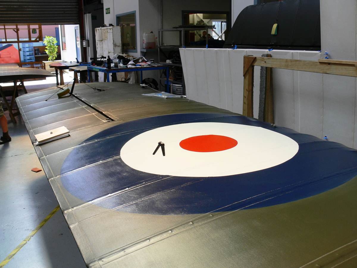
Image gallery of details from the FE.2b build process
“Todays’ aircraft manufacturers can purchase an engine, wheels , brakes, instruments and hardware directly from existing manufacturers. ”
At The Vintage Aviator we had to build nearly every individual FE.2b part. In most cases using the same materials and processes that were utilized in the original design, e.g. Irish Linen, ash and spruce timbers, hand spliced cables and original AGS hardware. As a tremendous bonus we were able to incorporate a number of original parts in our FE.2b such as the interplane struts, radiator shutter control, oil and fuel tanks, wheels and of course the beautiful and rare Beardmore engine.
“Our skilled craftsmen have learned to combine the trades of a bygone era with modern technology.”
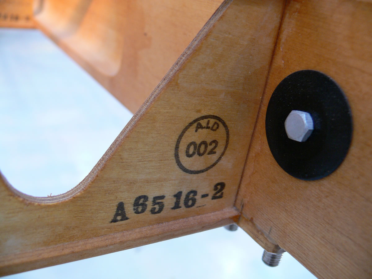
 In many cases even pushing modern technology to it’s limit by developing creative new uses machinery and technology available to us. As part of our production process we use 3D CAD design software, CAM programs and other specialized software through to CNC lathes, milling machines and routers all of which proved invaluble in this project. As one of only two CAA approved aircraft manufacturers in New Zealand we have some very strict guidelines and regulations to adhere to create a flying aircraft. This quality management structure allows for complete traceability and repeatability. Every single part is treated as a “job” and can be tracked through our shop, every process the part undergoes is outlined in our procedures manual, a lot to manage but with the help of our computerized system it adds value and precision to our products.
I doubt we would have even considered building an FE.2b if we didn’t have the proper engine, we essentially had four to choose from, the 120 and 160 Beardmore, an RAF 5a or Rolls Royce Eagle, all very rare. As luck would have it we were offered a 160 beardmore engine that turned out to be from an FE.2b ! This engine would have to be stripped, inspected and rebuilt while we got on with the rest of the project. Not only did we find an engine, it also came with some very interesting parts for the fee, a fuel tank, engine controls, radiator, exhaust system and even a prop.
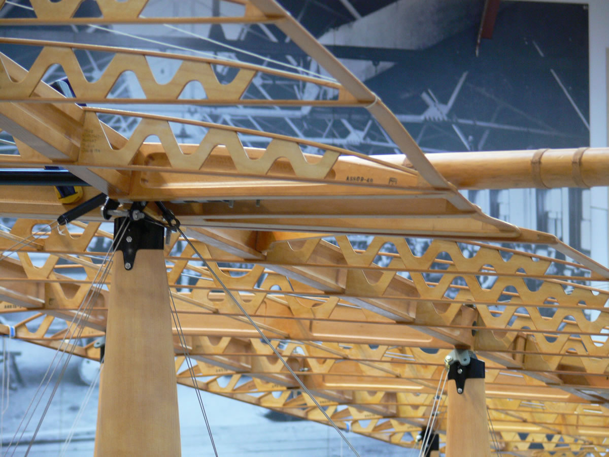
 Once the decision is made to begin a project no time is wasted and we start turning out parts. Relatively simple components like the wing ribs are started early on because of the great numbers required for an aircraft of this size. Tooling is constructed and tested to make sure our parts conform to the original drawings. These Jigs and fixtures aid final assembly and ensure assemblies are identical to each other and able to fit more than one airframe. Because we were building several aircraft at once, it was worth spending a great deal of time building decent jigs for parts like ribs, elevators, ailerons, cockpit carlins, and even entire wings. Even the decision to digitize certain parts in order to manufacture using CNC technology is something that we consider early in the course of the project.
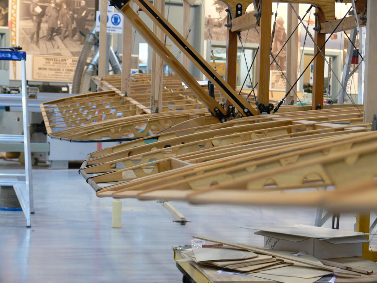
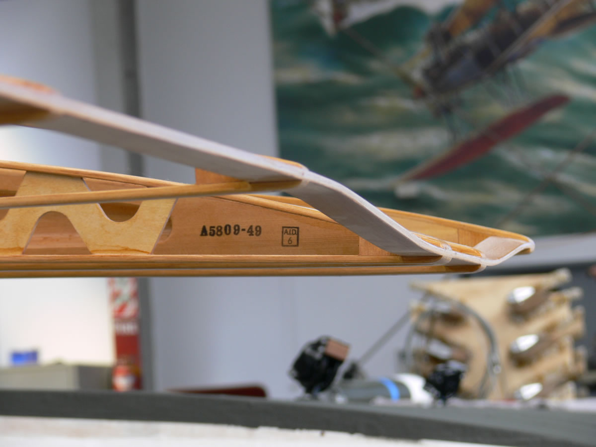
Fortunately the FE.2b uses wings that we already had in production! The BE.2 series of aircraft we are currently working have a number of different wing designs and airfoil sections but the BE.2c late style wings with the RAF 14 airfoil section are the exact panels used on the Fee. This was a big help since the ribs for these wing panels have simple plywood webs as opposed to the complicated built up ribs of the BE.2e . Our CNC router would be able to churn out rib parts in no time, this would be a simple profile cutting job using the vacuum table to simply “suck” sheets of plywood to the router bed while the computer automatically controls the cutting. After the webs are cut they are fitted with spruce capstrips and inserted in a jig for gluing. After a night in our temperature controlled room, ribs are removed from the fixture , cleaned and inspected.
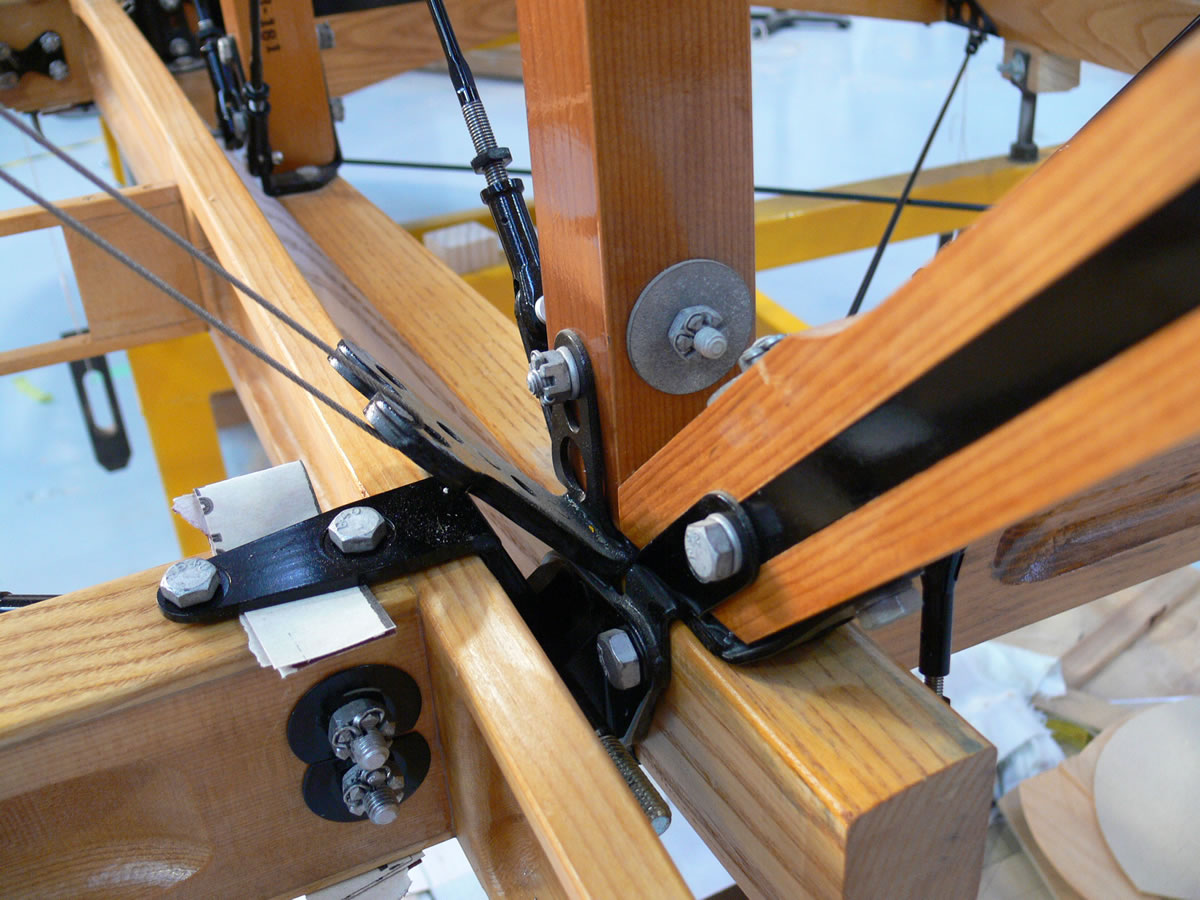
 As wooden parts were completed, we had to have associated metal bracketry on hand to test fit and finally assemble parts. We have good results using laser cutting and water jet cutting to produce multiples of each metal part required, this saves time, we then hand form them into finished clips, brackets and supports. It took many months to perfect the process of laser-cutting parts, but saved many years worth of labour! We had to learn all about “bend radius” and “set back” and a number of other variables that change with each material type used in the production of these aircraft. In some instances we have changed to proper aircraft grade steels but only because the lower grade steels are difficult to obtain with any certainty of their origin or of their composition.
The FE.2b has a remarkable number of parts in general and most of these are not found on any other aircraft. They are strangely unique to the Fee and difficult to reproduce, multi-layer steel fittings that have to “nest” together or that have tabs milled to accommodate universal wire ends, or even forged parts that have to be replaced with machined parts of suitable strength. One major manufacturing problem is the numbers of parts we needed, in some cases, one or two handed parts and in other cases hundreds of identical parts, a manufacturers’ nightmare!
 A single part often required experimentation and study before it could successfully be produced. For example, a simple wingtip, formed from laminated American white ash would be produced in a form and checked to see how much "overbending" was needed to end up with a part that matched the drawing exactly. This often meant creating several forms before the correct shape was found that would yield a suitable part. These types of parts are constructed by gluing several thin layers of hardwood together around a form and once dried, machining to shape. Glue tests are always made and we retain samples of every batch of glue we mix and the parts that have been glued with each mix. Many of these formed parts are then laminated to other parts such as spruce leading edges. For thicker hardwood parts steaming was required. With steaming we discovered that air dried timber versus kiln dried timber have different bending properties. A great deal of research and development work takes place on our part which can be applied to future projects.
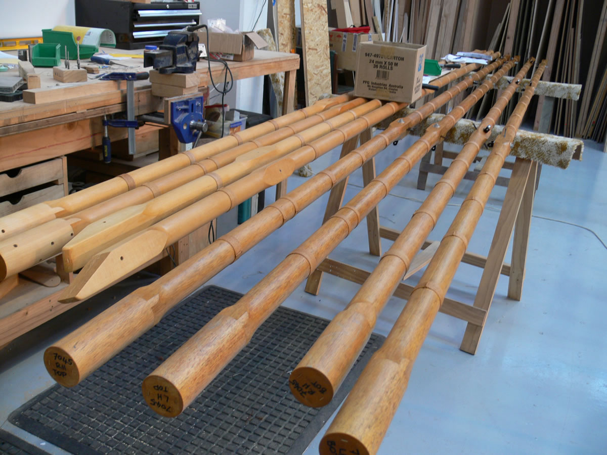
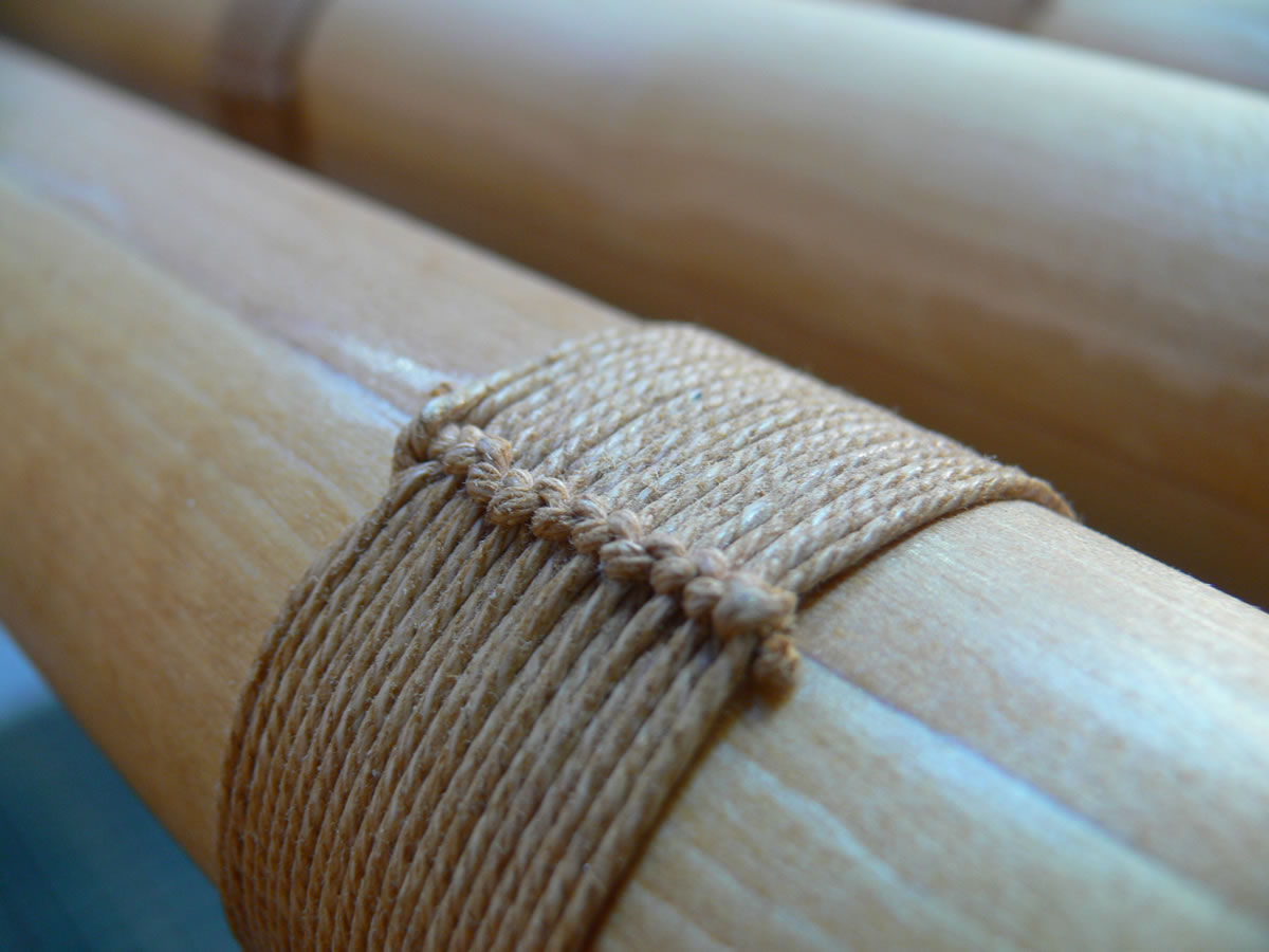
 The wooden cabane struts, interplane struts and outriggers were also machine carved on our CNC router. We use this for many wooden parts where repeatability and precision are required. The router can “rough” parts in a fraction of the time it would take to hand form them, and then we simply hand finish these machined parts. After the long spindly outriggers were routed to reduce weight, they get glued together to form a long square section. Prior to gluing, small strips of plywood are laid into grooves cut in the faces that will be joined, these strips aid in alignment, add strength and gluing surface area and prevent the glue joint from splitting open. The next process is the spindle molder, this machine turns the square section into the round shape of the tailbooms. These four structural members, braced with RAF wires and spruce struts, are nearly twenty three feet long and support the entire tailplane and tailskid arrangement. Since these flimsy wooden parts are so important every precaution must be taken to make sure they remain in good shape, linen cord is used to bind the outriggers at regular intervals and their condition must be closely monitored.

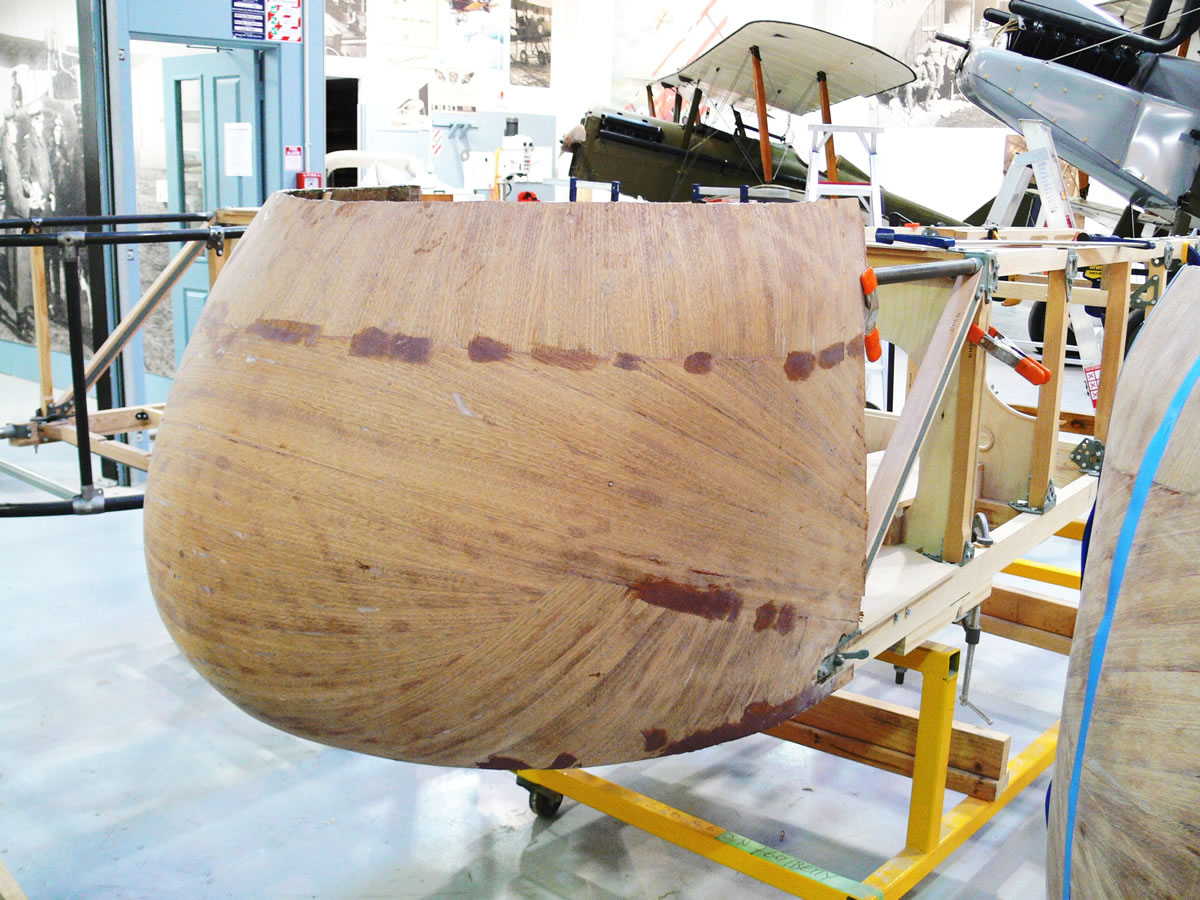
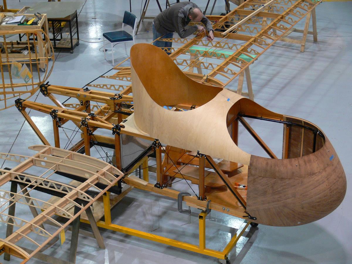
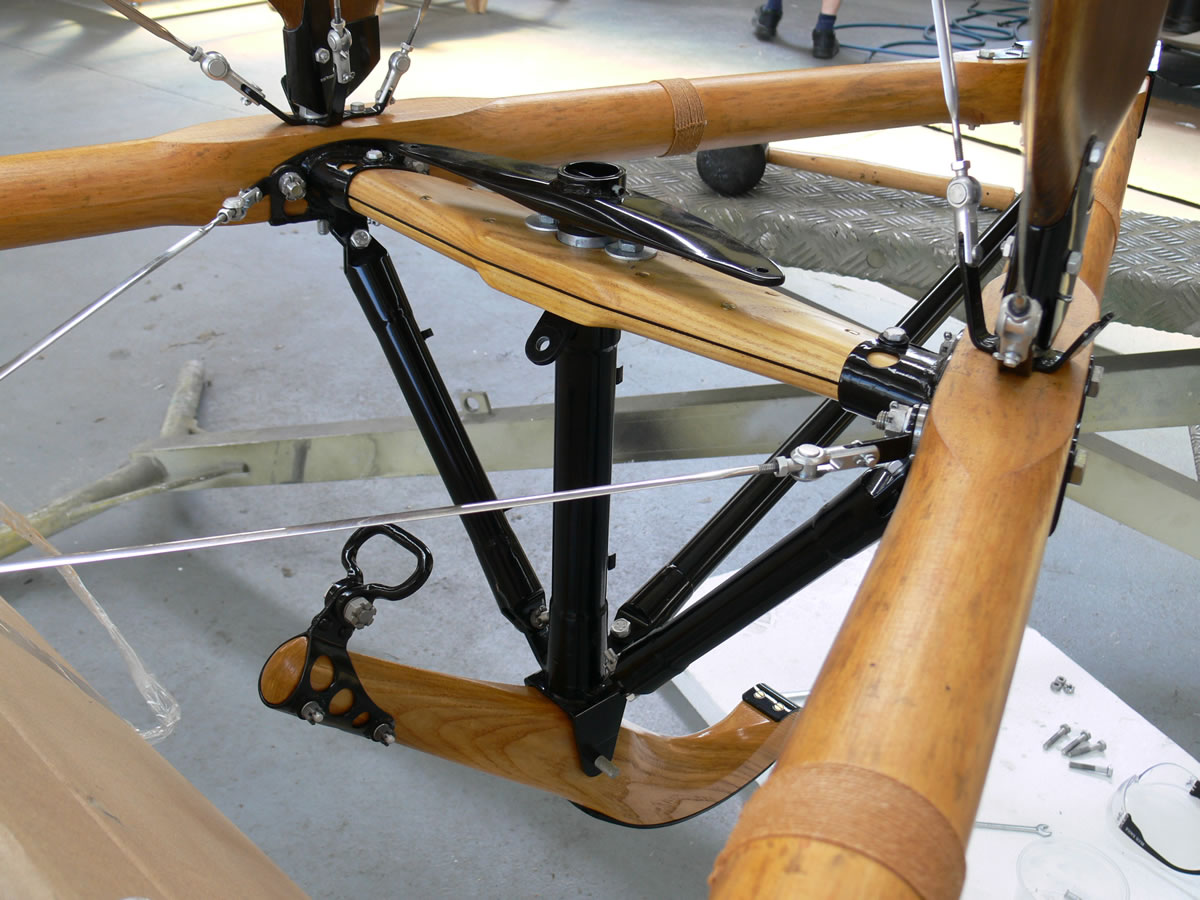
As the nacelle started taking shape it became apparent how different this aircraft was. The steel fittings were massive, the longerons short and stocky, the undercarriage could support a truck, and the engine was mounted in the back.
Some of the steel fittings were originally forged, which meant we had to find a suitable substitute, since we would rather machine them from billet than invest in a forging for the small quantities we required. Even building the fuel and oil tanks was a learning experience, these are constructed from terne plate and riveted together with copper rivets then soft soldered to seal them. The main fuel tank is pressurized to transfer fuel to the service tank and during flight, so it must be strong and carefully constructed.
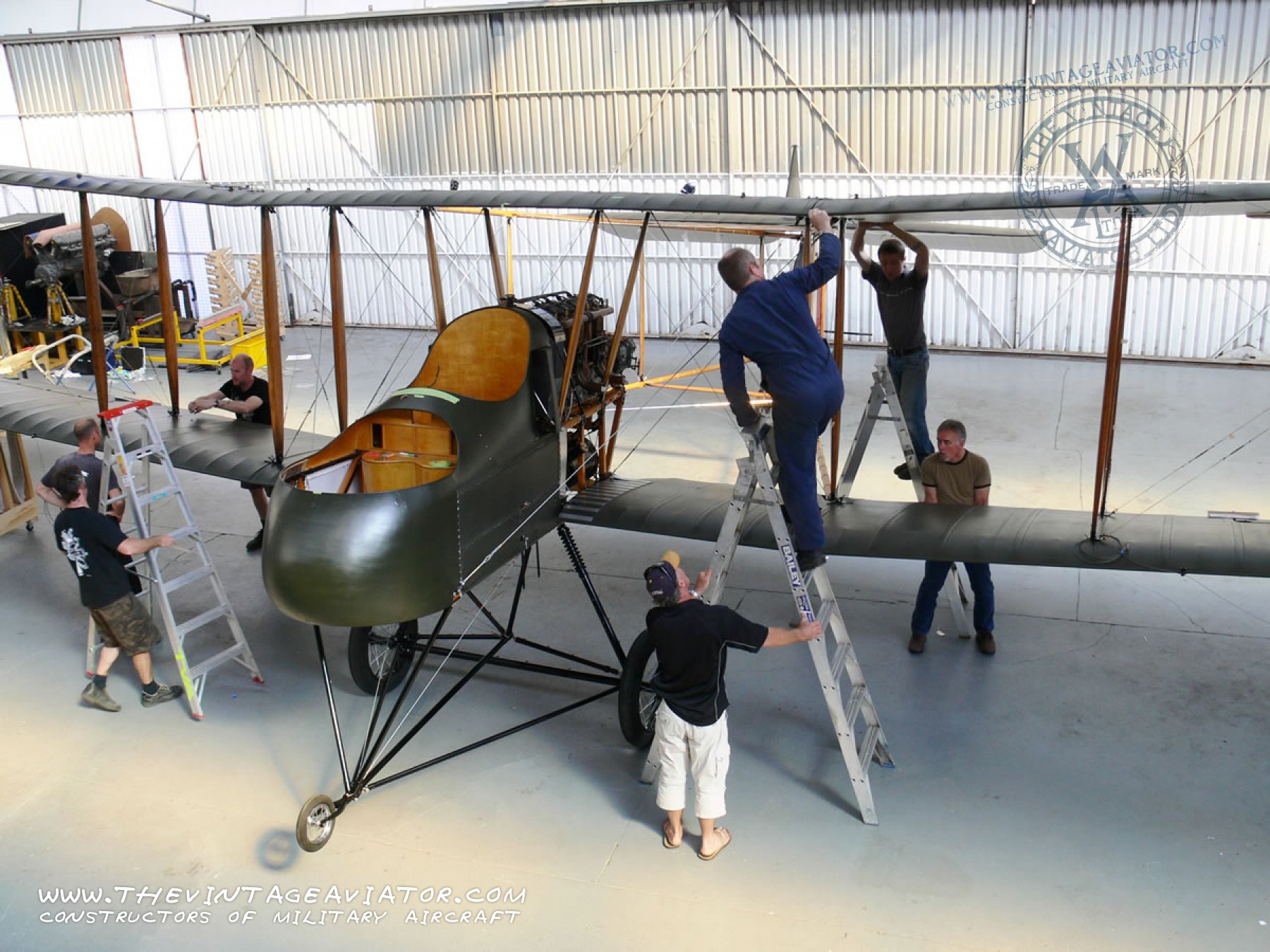
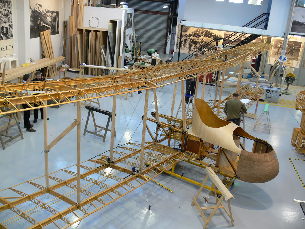
 Even the project plan for this airplane had to be creative, it is a very difficult machine to assemble, requiring a sequence of steps. As wing panels were finished they couldn’t be fitted until the sixteen foot wide upper centre section was completed, the lower handed centre sections are complex non parallel spar designs that took time to create and fit to the nacelle before the lower wings could be attached. Without the outriggers on there is nothing to support the tailskid or to mount the horizontal stabilizer or rudder.
 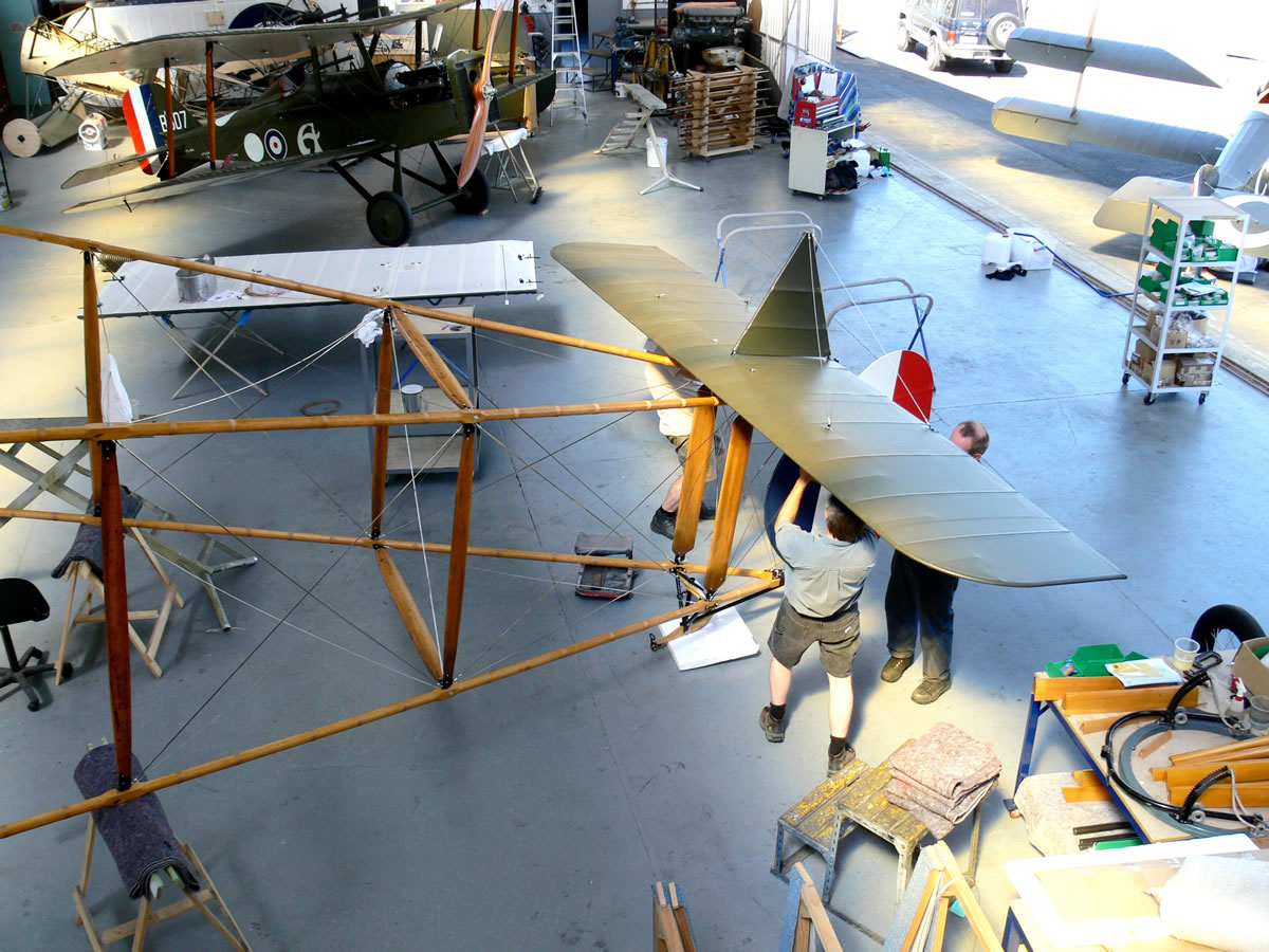 We would normally trial fit parts as we go but in order to keep to our schedule and build the entire aircraft in under three years, we had to trial fit some of the parts digitally in the computer. BY using CAD software to double check drawings and extrapolate dimensions that we were missing, we could keep many aspects of the construction process going simultaneously. Once the actual sub assemblies were completed we could check to see if our design work was adequate and it certainly was! The sheer size presented problems in our workshop, fifty feet wide, thirteen feet tall and a maze of wires created quite an obstacle course for our craftsmen!
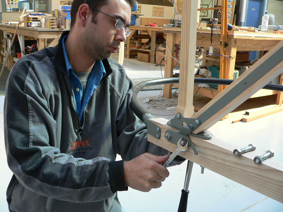
After months of converting hand drawn blueprints into digital images read on the computer, our design team found only minor dimensional errors on the original drawings.These mistakes were often hole sizes and such that would have been dealt with during assembly when “Fitters and riggers” would have assembled each aircraft by hand a very long time ago. Today we go through the same process of assembling major components and then fitting everything together as a complete aircraft, before it is covered with fabric. This process of “rigging” allows us to check RAF wire lengths, cable runs for interference, and of course the ability to position the wings and tailplane in the proper relationship to each other.
As the nacelle of the FE.2b took shape and parts like the aluminum pilots seats frame, leather seat cushion, and the big brass control stick was installed it became more personal, I would get a chance to fly this collection hand crafted parts, an exact reproduction of an extinct aircraft from the great war. This one of a kind airplane (at least until our second Fee is finished!) hasn’t been seen in the sky for nearly a decade. In the pilots cockpit the colors and textures bring you back to a time when plastic and vinyl didn’t exist; shiny copper tubing is carefully routed all over, brass control stick, air valve, fuel valve and magneto switches glisten, rich brown leather cushion and Sutton harness catch your eye, aluminum seat frame and nickel plated control levers dot the space and the big glass toped liquid filled compass becomes the centre piece of this aviators office.
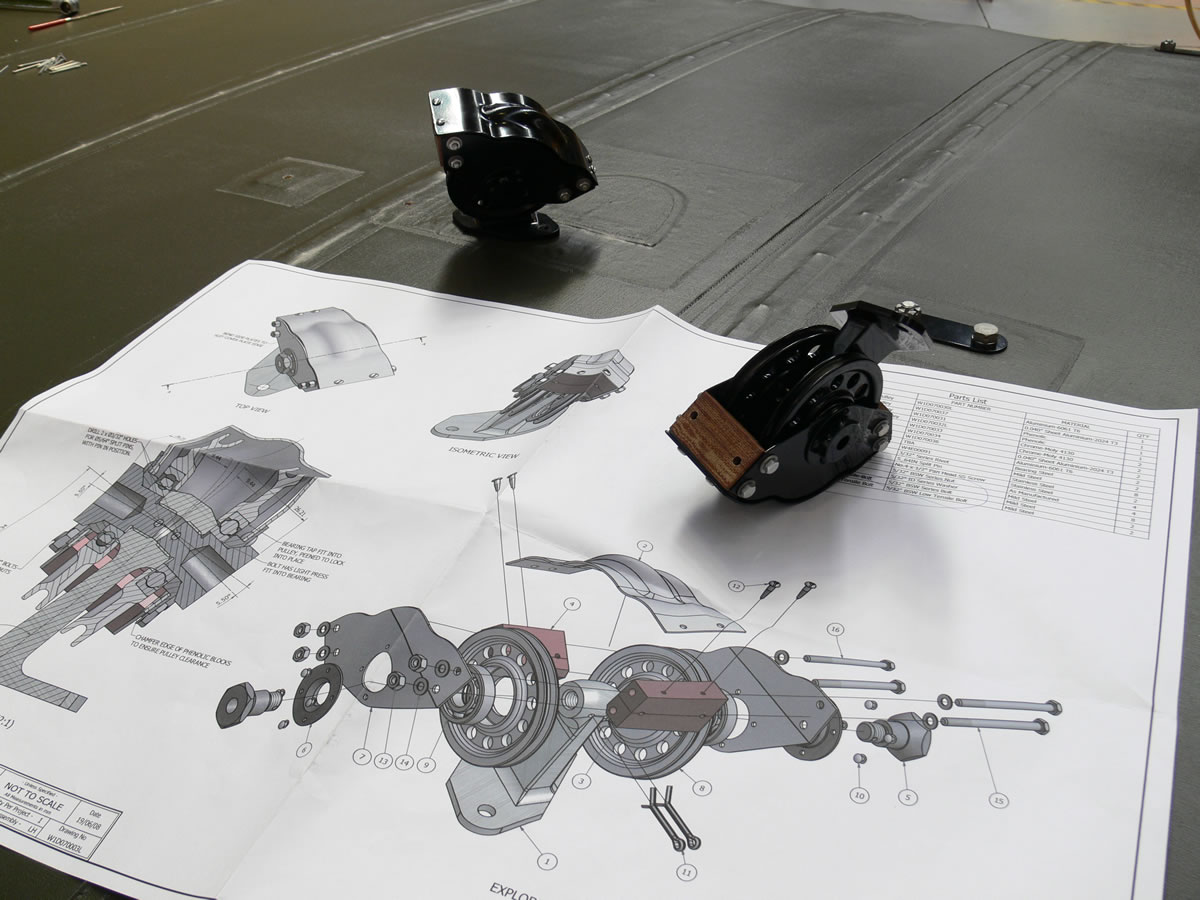
 The technology in this design is truly amazing, many parts I have never seen before on an early aircraft were incorporated into this one. The control horns that operate the elevators are huge welded steel streamlined parts on each side of the nacelle that fit onto a splined shaft connected to the control column. These splined shafts and their matching components are difficult to make, much like the control cable pulley housings. Two double pulley housings sit on top of the upper centre section to allow the elevator cables be routed back along the tailbooms. Incorporating odd angles, machined aluminum and phenolic cable guides and ball bearings each of these guides are critical to the look and operation of the Fee. The oleo undercarriage is perhaps the most complex landing gear I have seen on a WWl aircraft to date.
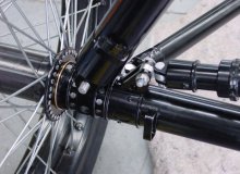
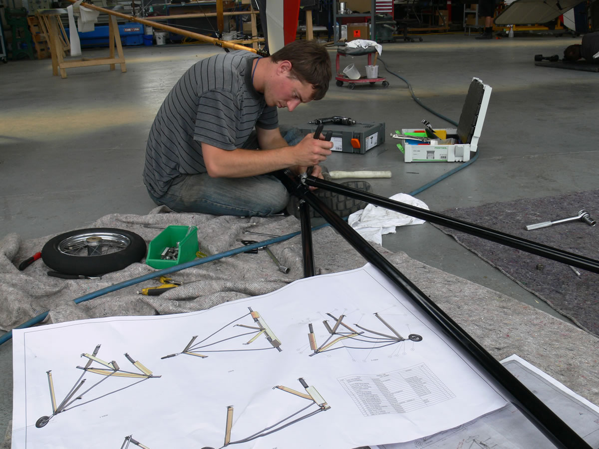
 The Oleo landing gear is made up of a number of steel struts, springs and seals. The entire system works to dampen each landing using long stroke main struts that extend nearly twenty inches assisted by a large springs for taxiing, these main struts are complicated parts, each having numerous leather and rubber seals, lock rings, gland nuts, and small pressure vessels. There are also several other struts that allow for minor crosswind correction, these struts incorporate springs to self centre the landing gear and allow the undercarriage to be very forgiving. The geometry of the landing gear was one of the major components that we completely modeled in the computer before we made the first part, it simply didn’t look like it would work!
The fee has all sorts of fairings to cover rather blunt, unstreamlined parts that wouldn’t normally be seen on a plane. Big spruce fairings on the landing gear legs had to be hand formed and then wrapped with thin aluminum, tiny aluminum bullet shaped shroud fro the little air pump under the nacelle and those iconic “UFO’s” the weird little pulley housings found all over the fee. The rear part of the nacelle was as difficult to form as the front, this time it had to be done using thin aluminum hand formed by welding, rolling, and using and English wheel and planishing hammer.
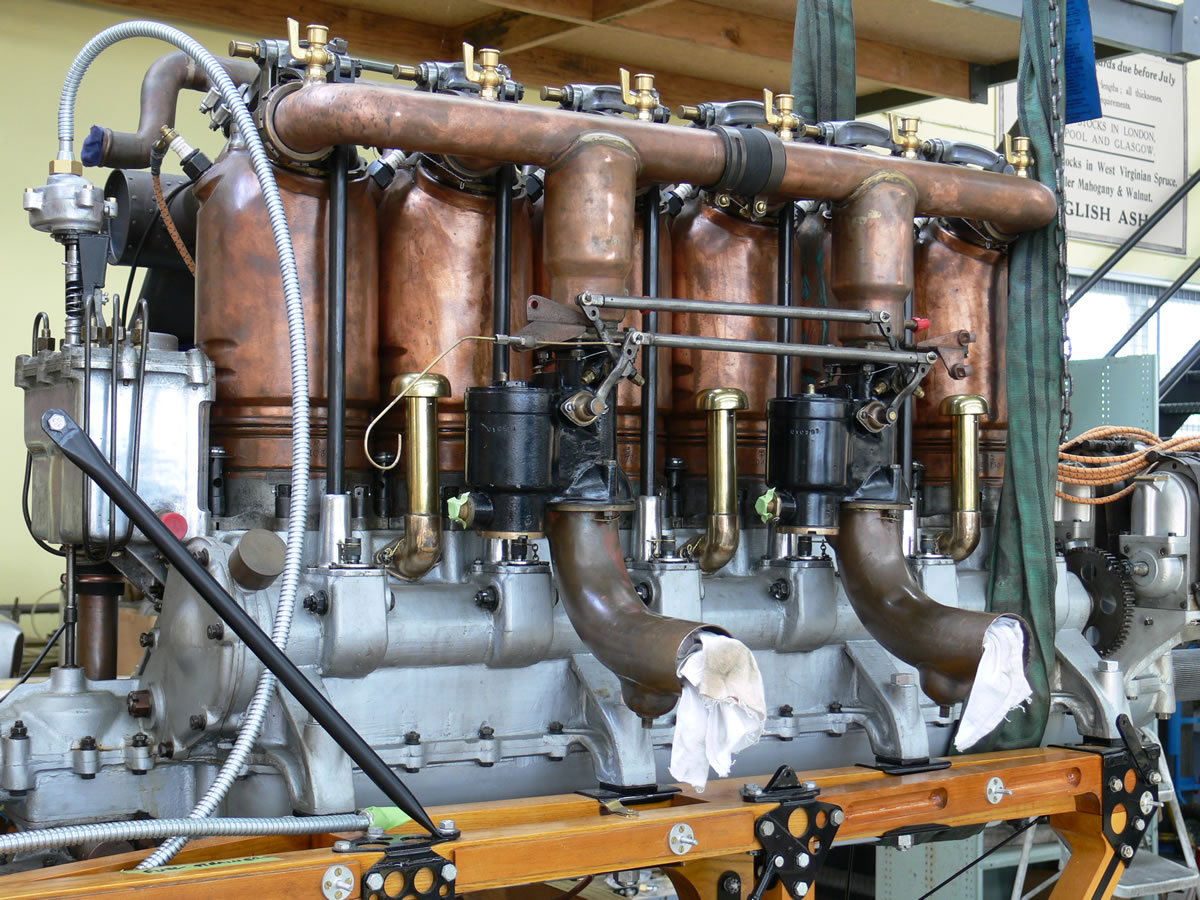 Our second fee would need an exhaust system and oil tank, these would be hand formed out of steel. The exhaust stack on the beardmore is attached using large brass gland nuts which had to be made and then incorporated into the exhaust manifold as it was crafted.
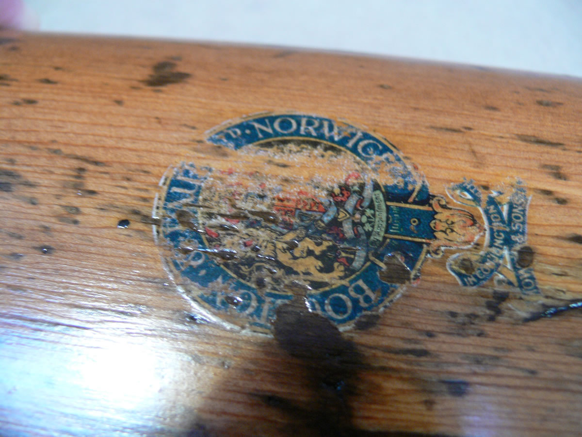
As we collect more and more original parts we are faced with all sorts of issuse regarding conservation and restoration. The two concepts vary slightly; conservation is where we apply treatment or processes in accordance with certain preservation ethics and standards that are intended to protect the history and integrity of the object, restoration is whereby we return the object to its earlier appearance or to working condition. In some cases the two concepts go hand in hand. In the case of the FE.2b we felt that original airworthy components are best suited as integral parts of our finished aircraft rather than some individual nondescript part that would remain in storage or part of a display that doesn’t necessarily represent anything significant. Parts that we don’t use are still valuable resources of information, they help us to determine manufacturing techniques, finishes, materials and all sorts of things, we take great care in preserving these items as part of our conservation process. Many museums and collectors have components that never become part of an exhibit or get shown to the public because they aren’t particularly interesting on their own, in our case these are just the sort of items we use most for reference and to complete our projects.
We are lucky to have access to an original FE.2b propeller, which we scanned into a computer and then machined exact copies from laminated mahogany for each aircraft. The engine had to be carefully inspected and then overhauled and test run prior to installation in the airframe. The TVAL manufactured prop had to be tested to make sure that it performed as good as the original and to “break” the engine in.
One aspect of aircraft construction that is often overlooked are all of the “accessories” and minor details that make these aircraft so special. We build our own water temperature gauges, tachometers, airspeed indicators and almost every other cockpit instrument that may be required. We also fabricate hand air pumps and the small wind driven air pups that pressurize the fuel tanks and make our own Mk lVa gun mounts. To TVAL the details are essential, even the Irish linen and the colors are researched so that we can faithfully recreate each aircraft. The cockpits are adorned with several spare Lewis magazines and accurate Brooklands windscreen, original Thomson Bennet magneto switches and a proper Sutton harness.
 The FE.2b is a fighter and as such, it could be said the guns are the heart of the airplane. The twin Lewis guns are highly visible in the front cockpit. Real Lewis Guns create legal problems , so we decided to manufacture our own and retained the option of fitting a real blank-firing gun for airshows. We also replicated the original MKlV bag that catches the spent shell casing, an important accessory on a pusher design.
 This exceptional project was a massive undertaking comprising years of work and determination, much longer than the mere months it would have taken ninety years ago. The Vintage Aviator craftsmen spent years building this perfect example, even with modern machinery and computers the work is still predominantly done by hand. The guys have lots of feedback on the shop floor, the level of finish and workmanship is stunning, everything from the complicated joinery work to the machined finish of the steel parts even the welding and fabric work is second to none and many of our guests can’t help but comment on their superior workmanship. By creating new drawings from old and reverse engineering parts from originals, we are preserving these historic machines for future generations to enjoy. In some way we are just stewards of these machines and parts for they will outlast us.
“A few have said this is a “people” airplane and it really is all about the guys up front in this machine. Exposed to the elements and clearly visible, the guys that operated these “string bags” nearly a hundred years ago were true Aviators.”